Every report, inspection record, and capital document we produce is anchored to a zone diagram specific to that building. The diagram is the permanent reference that survives
A photograph of a roof defect is not useful documentation if you cannot locate it on the roof. An inspection report that says 'flashing deterioration at northeast parapet' is not useful if the building has 400 linear feet of northeast parapet and you cannot tell which section the report is referring to. Zone diagrams solve this problem by creating a numbered reference system for every section of the roof that every subsequent report can anchor to.
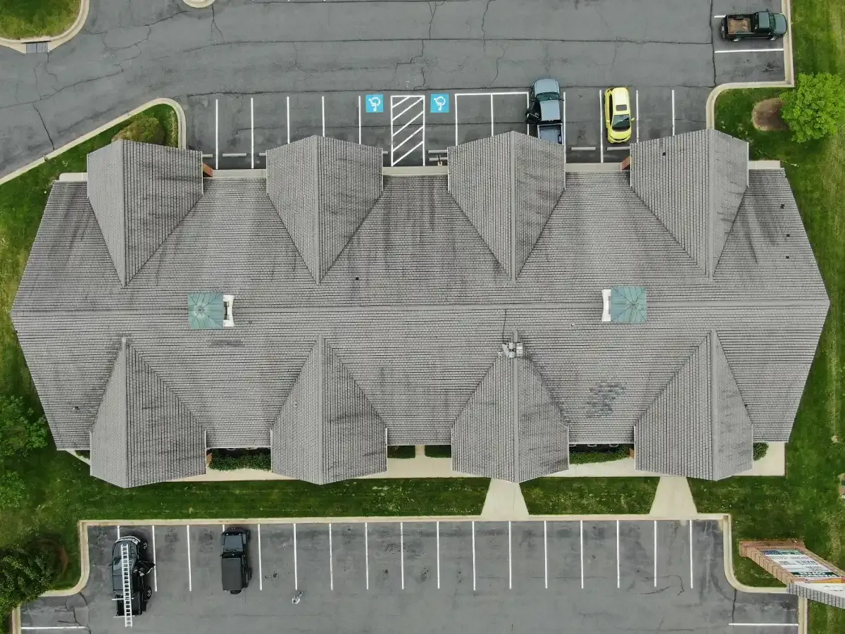
Zone mapping is the first step on every building we add to our inspection program. Before the first inspection report, we produce a zone diagram keyed to the building's actual roof layout — its physical dimensions, drain locations, mechanical equipment positions, parapet geometry, expansion joints, and roof access points. The zones are numbered sequentially and sized to meaningful physical boundaries: an expansion joint defines a zone boundary, a drain cluster defines a zone, a mechanical equipment island defines a zone.
The zone diagram is then used to anchor every photo in every inspection — each photo is labeled with a zone number and a defect descriptor. Every scope item is logged by zone number. Every core sample is plotted by zone number. When the fifth inspection on the same building references 'zone 7,' everyone working from that inspection knows exactly where zone 7 is, what it looked like in the four prior inspections, and what the current report says about it. That consistency is not possible with undifferentiated photo dumps or narrative-only reports.
We start with the building's roof plan if one exists — from the original permit set, from the property's as-built drawings, or from the building's facility team records. If no plan is available, we measure the roof geometry on-site. The diagram is then drawn to scale with roof section areas labeled (in square feet per zone), drain locations marked, rooftop equipment positions marked, and roof access points marked.
Zone numbering follows a consistent convention: zones run north-to-south and west-to-east, numbered sequentially so that zone 1 is always the northwest-most section. Sub-zones within a main zone (for example, the parapet return within zone 3) are designated with a letter suffix: zone 3A (field membrane), 3B (parapet return), 3C (drain detail). This gives us a zone-level reference for field conditions and a sub-zone reference for specific details that need individual tracking.
For buildings with multiple roof levels — a main roof plus a lower canopy or an attached building wing — each level gets a separate zone diagram with a building-level prefix so zones on the main roof are '1-' prefixed and zones on the lower wing are '2-' prefixed. This prevents zone-number collisions across a complex building footprint.
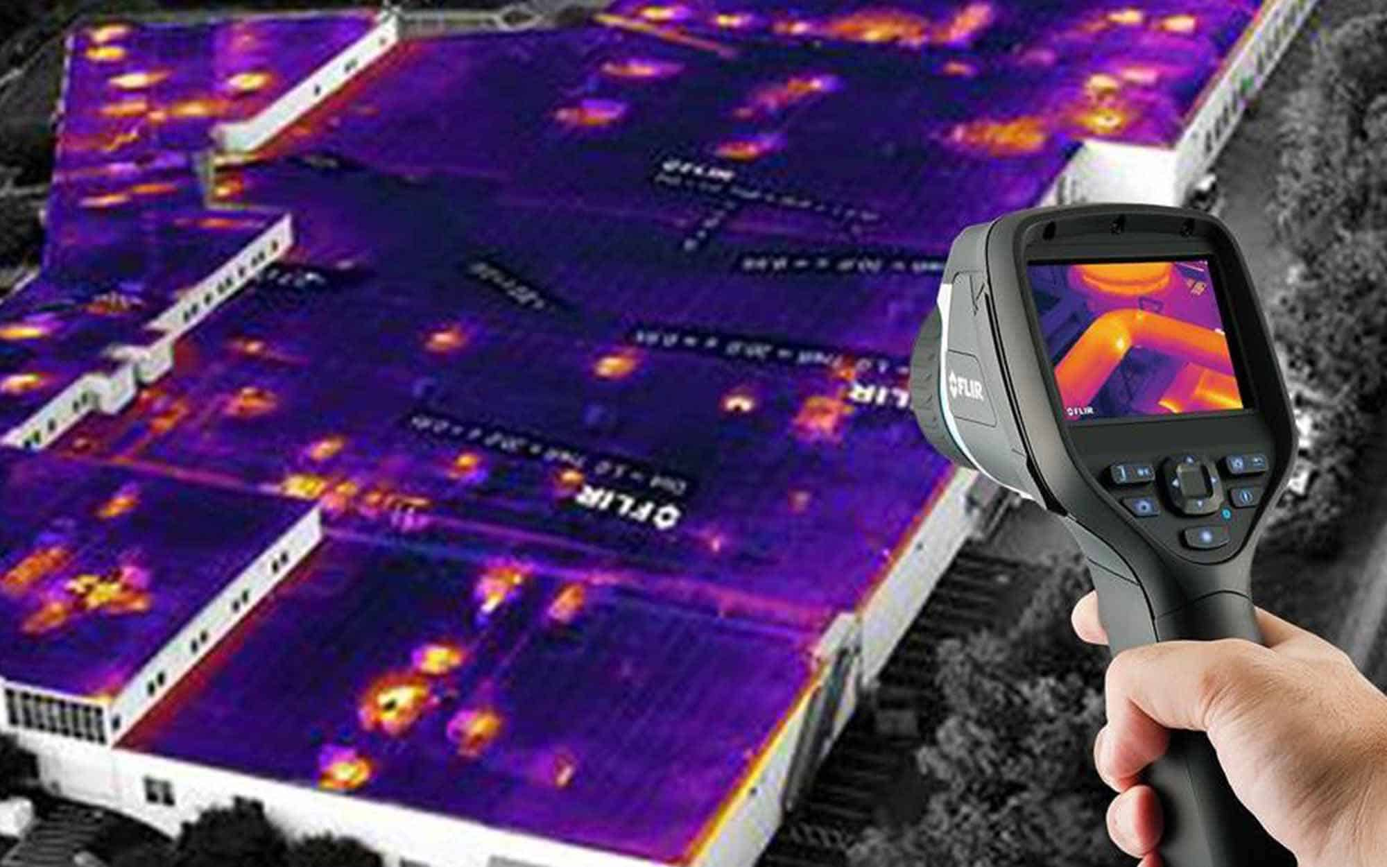
Every photo in every inspection report is labeled with the zone number and a brief defect descriptor. Photos are organized in the report by zone number so a reader can navigate the report geographically — find zone 7 on the diagram, turn to the zone 7 section of the photo log, see every photo from that zone in sequence.
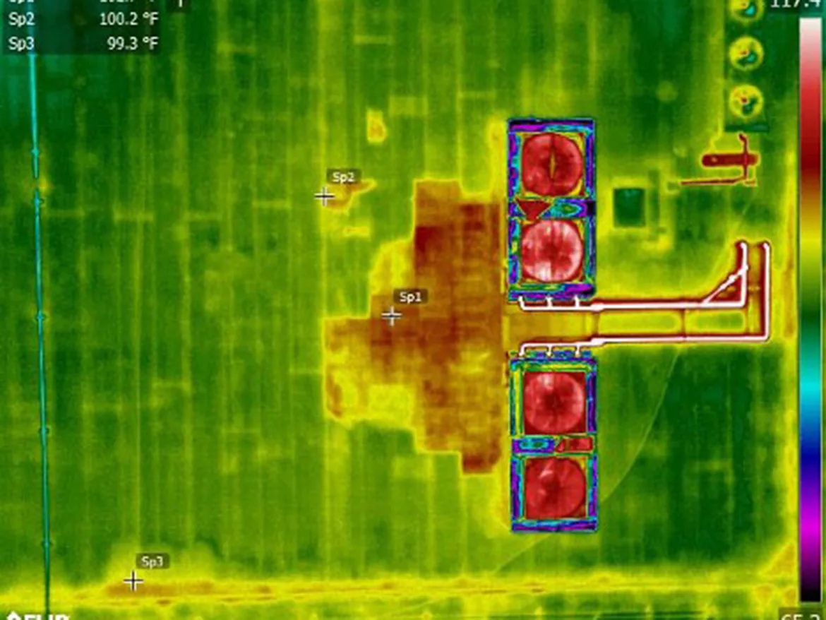
We photograph every zone on every inspection, including zones in good condition. The absence of defect is documentation — if zone 7 has a pristine seam and no flashing issues in three consecutive inspections, that record is useful when zone 7 eventually develops a defect, because the trend data shows when the deterioration started. It is also useful in a warranty claim, because the manufacturer's field inspector can see that the area in question was in good condition as recently as the last inspection.
For buildings where we are taking over from a prior contractor, we establish the zone diagram on our first inspection and note which zones were photographed versus which we are documenting for the first time.